Making Your Apartment Buzzer Party Friendly With Raspberry Pi and Twilio
Time to read: 5 minutes

To fix her buzzkill of a buzzer, Amy and her friends put their heads together and built a Twilio powered solution that triggers Amy’s apartment buzzer by texting a password to a Twilio number.
Below is Amy’s tutorial originally posted on GitHub here.
How To Set Up A Buzzer Bot
Chances are if you have a Raspberry pi, and you’ve done anything at all with it, you’ve turned on an LED. This project is almost as simple as that. The software requires a some set up, but hardware-wise, if you can turn on a LED, you can do this.
You’ll need:
- A raspberry pi with Node js installed
- A domain from freedns
- A twilio account with a phone number
- An optocoupler (I used this one)
- Some resistors
- An LED
- Breadboard
- Wire
Step 1: Install Stuff!
See the read me for the basics of installing this code on your pi. Once you install it, rename sample_config.json');">[crayon-5b6d1f3150cbd895078682-i/] to config.json. You’ll need to fill in the blanks, but we’ll get to that later.
Step 2: Set Up Your Test Light
Before we connect anything to your buzzer box, let’s set up a simple test light to make sure the software is set up right.
All we need right now is to get one LED turning on and off, so I’m going to defer to another tutorial because there are lot of great ones already. This is the one I used, but if you find another you like that’s fine too. Once you have an LED connected to your raspberry pi, come back here.
Now that you have an LED turning on and off, open config.json, and change buzzer_pin to the physical pin number your LED is connected to. If you used the tutorial I mentioned above, your number is 11. Otherwise you can use this handy digram to figure it out. The numbers in the circles are the physical pin numbers.
Then, run node test.js and your LED should turn on for 2 seconds, and then turn off.
Step 3: Finish Software Setup
Now that we can test it, let’s get it hooked up to Twilio.
Routing
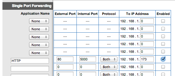
First you need to let your raspberry pi out onto the world wide web via your router, so twilio can get to it. I can’t really tell you how to do this for your router, but you want to open up a port, and send that port to your raspberry pi’s ip address. You’ll probably need to give you raspberry pi a static ip on your local network.
Here’d how I did it on my router:
First I went to DHCP Reservation…


DDNS Service
Go to freedns and find “Dynamic DNS”. At the button hit “[ add ]”. Leave the type as “A”, pick a subdomain (this can be whatever you want), pick on of the public domains (again whichever you want), and leave the destination (we’ll update it from the pi).
Once you’ve saved it click on “Dynamic DNS” again and find the “Direct URL” for your subdomain. Copy everything after the ? into freedns_key in config.json.
Then run ./bin/cron_install');">[crayon-5b6d1f3150cd7884045659-i/] which will install a cron to update the ip your DDNS points to periodically.
At this point you should be able to run npm start on your raspberry pi and you’ll see some stuff like this:
Once that’s running you should be able to go to /sms in a browder and see Webhook Error - we attempted to validate this request without first configuring our auth token. and see this in the console [Twilio]: Error - Twilio auth token is required for webhook request validation.
Twilio
Now we need to point Twilio at the domain you just set up. Go to Twilio and set up a number. Then go to the settings for that number and set the message request url to /sms:

Also grab your twilio Auth Token and fill in twilio_token in config.json.
Now when you run npm start and go to your domain it should say Twilio Request Validation Failed., and if you text it, you should get a message back saying “Hmmm, that’s not a password” but! If you open up config.json and put your phone number in the “sesame” allow list, and then text “sesame” your test light should come on for a few seconds and go back off.
Step 4: Buzzer Box Time
Now you need to connect your optocoupler to your raspberry pi and your buzzer box.
Your optocoupler has two sides: one side has an LED, the other a photo resistor. When you turn the LED on, the resistor connects the leeds on the other side. Your buzzer box has a “door” button. When you press the door button, it connects two wires and the door opens.
What we want to do is connect the LED side of the optocoupler to the raspberry pi, and the photo resistor side to the door button. The raspberry pi will turn on the LED, which will connect the sides of the door button, and the door will open. Magic!
Here’s a diagram and an up close look at my wiring:
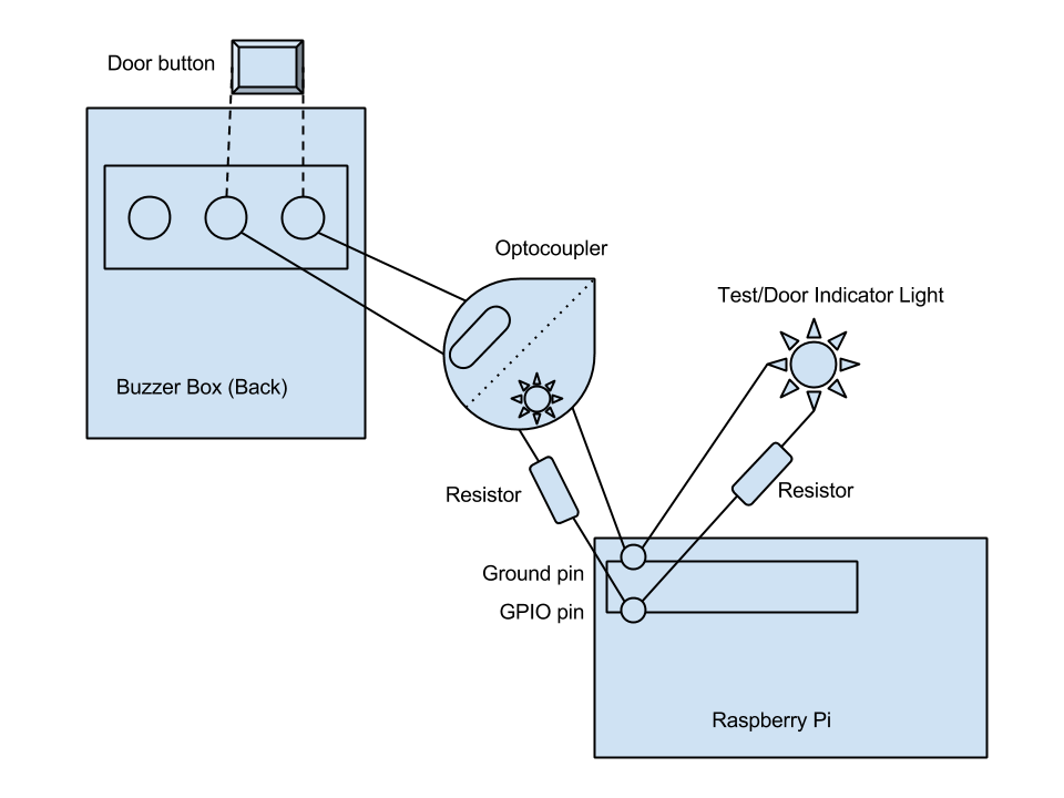
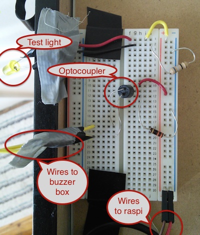
Turning on the optocoupler is the same as tuning on a single LED. So you’ll need a resistor between it and your raspberry pi. If you are using the same optocoupler, you’ll need one 33 ohm resistor. If you’re not, you’ll need to figure out the resistor value yourself. Here’s a handy single LED series resistance calculator. Source voltage is 3.3 volts, and you should be able to find the forward voltage, and the forward current on the data sheet for your optocoupler.
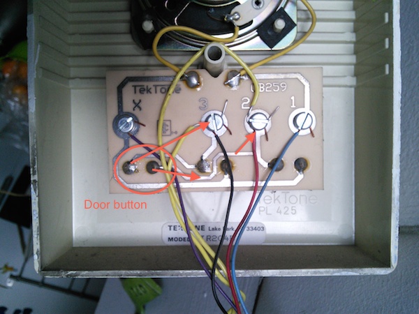
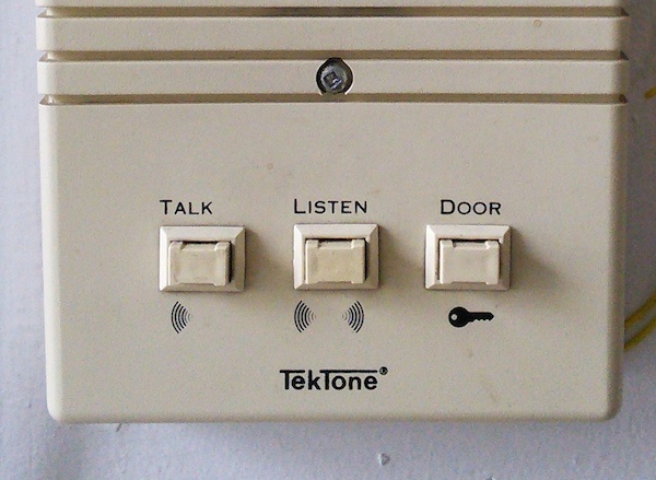
Here’s a real life picture of my buzzer box. It’s a very simple box made by TekTone that most people I know have, but if your is different, don’t worry. You just need to find the two contacts on the sides of whatever button opens your door.
The light yellow wires (connected to #2 and #3) are the ones running to my pi. Either of these wires can go to either wire on the photo-resistors side of the optocoupler because photo-resistors are non-polarized.
Step 5: Put It All Together
Now you should have almost everything hooked up, installed and configured. Run nmp start again, go outside and test it!
The one last thing to do is run ./bin/initd_install');">[crayon-5b6d1f3150cf8462429974-i/] which will install an init.d script to /etc/init.d/buzzerbot_init.sh. This will make your buzzzer bot server run whenever your raspberry pi starts up.
Something isn’t quite right? Did I leave something out? Be awesome and submit a pull request with a fix/addition to make things more clear.
Thanks for follow this tutorial and let me know if you actually get this set up!
Extra Pictures
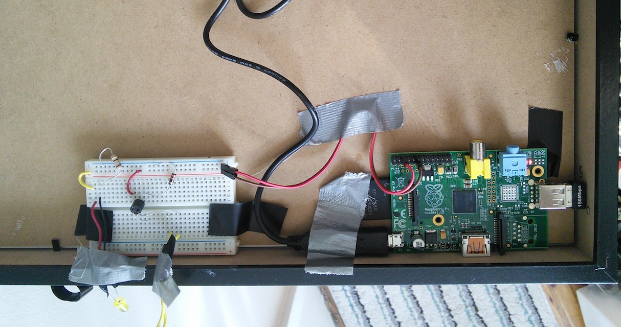
Here are some pictures of mine set up! I have my raspberry pi behind a deep picture frame that hangs above my buzzer box.
Related Posts
Related Resources
Twilio Docs
From APIs to SDKs to sample apps
API reference documentation, SDKs, helper libraries, quickstarts, and tutorials for your language and platform.
Resource Center
The latest ebooks, industry reports, and webinars
Learn from customer engagement experts to improve your own communication.
Ahoy
Twilio's developer community hub
Best practices, code samples, and inspiration to build communications and digital engagement experiences.
