DIY Home Automation Using Twilio, PowerSwitch, Arduino, and Pusher
Time to read:
This post is part of Twilio’s archive and may contain outdated information. We’re always building something new, so be sure to check out our latest posts for the most up-to-date insights.

Need a primer? Take the Twilio SMS Docs for a spin here

You may have seen my recent blog post about building a Phone-controlled Robot using Twilio. Since then, I’ve had ideas for new Twilio + Arduino mashups pouring in from the community. Today is the second post in our new series of Twilio Hardware mashups – build your own home automation solution using Twilio SMS, PowerSwitch, Arduino, and PusherApp.
Last week I left the A/C in my apartment on while at work. All day, I was wishing I had remembered to turn it off for the sake of my electric bill. But alas, I was out of luck. If only my A/C were able to be controlled from some sort of distributed network.
Lucky for me, Al Gore invented the Internet (100% better than ARPANET for home automation). While there are consumer home automation utilities out there such as Belkin’s WeMo, I decided that it would be more interesting and enjoyable to build my own. It would have been selfish of me to keep this to myself, so I wrote it up in the tutorial for the good of the internets.
First off, here is a video of the final, working version of the project (I recommend watching it in 1080P so you can see the debug console output):
As we release more of these tutorials, you’ll notice that some have more complex hardware and some have more complex software – I’ll do my best to keep them varied and interesting for all of you amazing hardware hackers out there. For those of you looking for the flying robot that Techcrunch mentioned…don’t worry, its coming.
When you finish this tutorial, you will be able to turn on and off a power outlet using Twilio SMS or a simple web application. Also, please note that electricity is dangerous – I recommend that you don’t crack open your PowerSwitch, it is designed to safely handle 120vac power but human bodies are not. That being said, lets jump right in!
The Parts
You will need the following parts to build your application – while its a decent upfront investment, all of the parts are reusable for future hardware experimentation and fun:
- PowerSwitch Tail II
- RN-XV WiFly
- Wireless SD Shield
- Arduino Uno SMD w/ USB Cable
- M/M Jumper Wires
- 5V FTDI Cable
- 9V Battery Adapter
- A small flat-head screwdriver
Note that the one part you do not need is the FTDI Cable, but I found it very useful for debugging my Arduino over alternative Serial pins while using the WiFly chip, which takes over the standard hardware Serial.
The Hardware
The hardware setup is pretty basic and requires no soldering. The first few steps are very similar to the robot tutorial as they cover basic initial setup – feel free to skip to Step 3 if you’re comfortable setting up an Arduino.


Step 6 (Optional): Plug the other end of the green cable into the port where the FTDI cable’s yellow wire ends (RX). The other end of the brown cable goes next to it, where the FTDI cable’s orange wire ends (TX). These are the 2nd and 3rd from the green end of the FTDI cable.


It’s Software Time
Firstly, you will need the Arduino software to download your code onto your chip. Then you will need some libraries to communicate with your RN-XV WiFly chip.
For this tutorial, I decided to use the WiFlyHQ library by harlequin-tech and to borrow their examples as a boilerplate. This library allows the Arduino to connect to a WiFi network via the RN-XV module. We then connect to the Pusher service which will trigger an event when an SMS is received or a form button is clicked on a website. I used Pusher rather than a simple TCP server because I found it easier to debug and more stable, I also wanted to experiment with using Arduino and WebSockets.
In order to get the Arduino to connect to Pusher successfully, I forked krohling‘s ArduinoPusherClient (designed for the Ethernet shield) and modified it to work with the WiFlyHQ library. I also included the WiFlyHQ library in my repo for ease of use so you do not need to download them separately.
First things first, you will need to download my modified ArduinoPusherClient library and place it in your Arduino library directory. Then we can dive right in to the sketch, just start out by opening up a new file in the Arduino IDE and add the following code:
The beginning of this sketch is straightforward – we initialize our output pins for the PowerSwitch and our status LED, and we initialize our WiFly to ready it for instructions. I am using SoftwareSerial as a workaround to get debug output while the RN-XV occupies the hardware Serial pins (0/1) that the Arduino normally uses for debug output. You will need to put in your WiFi credentials and Pusher API key in the defines at the top of this sketch. Next you can go ahead and add the following code to the end of our setup() function. This snippet joins a WiFi network and then connects to pusher, subscribing to our robot_channel channel. It then binds to the powersms event which will be triggered upon receiving an SMS.
Our setup() function was the most complex part of our sketch, in fact our loop simply monitors the incoming TCP requests for events and then turns on the LED if we have a successful connection:
All that is left now is to add our powerSwitch() callback function, which receives event data from Pusher and responds by turning on or off our power outlet. You will note that we are using a PusherClient function called parseMessageMember – this is an extremely basic parser for the JSON event data being sent along by Pusher. There is an Arduino JSON library but it was exceedingly complex for this application. In the following function we are taking the data string and retrieving the command parameter from it, which is what tells us whether to turn the outlet on or off – in a production example, you will likely want to implement some sort of security check here so that you make sure only verified users are controlling your device:
You can now upload your sketch to the Arduino using the included USB cable (plug the fat end into the Arduino and the USB end into your computer) and then plug in the RN-XV module if you have not done so already! You can find the full sketch file here for reference.
(Optional): In order to get debug output from your FTDI cable via SoftwareSerial, you will need to install the FTDI Drivers first. You will want the VCP version of the drivers.
The Server
The server is a very basic application written in Ruby using Sinatra and hosted on Heroku. The first thing to do is set up basic configuration with our Gemfile and Procfile:
Now you can go ahead and create twilio-power-outlet.rb and add the following code:
In this snippet we are setting up our Pusher configuration variables and including necessary gems. We will set up the environment variables later when we push to Heroku. Next we can go ahead and set up our ‘/control/’ route, which receives incoming SMS or form submissions from our basic web page. You’ll notice that we output errors to TwiML SMS or web depending on how your request was submitted.
Last but not least, we need to define our index route, which displays our index.erb template containing a form to control the power outlet from the web:
Once your twilio-power-outlet.rb file is completed (check it against the complete example here) you can create a views directory and set up our index.erb file, which displays a form to control the power outlet from the web:
Now that our scripts are complete, we can retrieve our Pusher account credentials, set up our Twilio number, and push our app to Heroku. First things first, you will need to install the Heroku Toolbelt, which includes git and heroku. If you have never used Heroku before, I recommend checking out Heroku’s Getting Started document that shows you how to set up an account and log in for the first time.
Once you have that installed and set up, you can execute the following commands to add your files to a new git repository:
Then you can run these commands to create a new Heroku application and push your code to the server:
When your git push is finished executing, you should see a line similar to this: “http://blazing-galaxy-997.herokuapp.com deployed to Heroku” – that gives you the URL of your new Heroku application.
Take this URL, add /control/ to the end, and enter it into the SMS Callback URL for your Twilio phone number.
If you are brand new to Twilio I recommend watching our SMS Quickstart Screencast which shows you how to buy a number for the first time.

Next you can head over to your Pusher dashboard and get your API Access Key. If you have not used Pusher before, you can sign up at pusher.com. Note: Never share your API credentials (I changed mine after taking this screenshot, don’t worry)

And last but not least you need to set up some Heroku environment variables. First, you should go back to your Arduino sketch and update your pusherKey variable with the information from your Pusher dashboard.
Then take the app id, key, and secret from Pusher and replace where necessary in the following shell commands, then run them from your Terminal:
Your output should be similar to this: “Setting config vars and restarting twiliopoweroutlet… done”
Now you should be all set to go. You can head over to your Heroku URL and should see the form to turn your Arduino on and off. If you’re curious about whether the Arduino is actually connecting to Pusher, you can use your Serial Monitor for debug information or use the Pusher Debug console for information on their end.
Optional: Debugging with your FTDI Cable
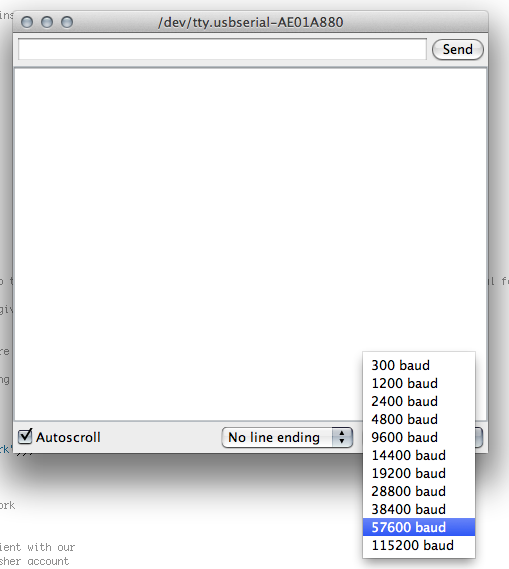
As I mentioned throughout the tutorial, you can use your FTDI cable as an alternate Serial port to get debugging output from your Arduino. In order to do this, you will need to follow the optional wiring steps above, and then plug the USB end of the FTDI cable into your computer after installing the FTDI USB driver. To see the output, have your Arduino plugged into your computer via both the included USB cable (for downloading sketches) and the FTDI cable. Then, when you are in your Arduino IDE (the Arduino should be on), go to the Tools menu, then the Serial Port submenu, and select /dev/tty.usbserial-##### – this is the FTDI USB port.


Then, when you restart your Arduino you should start seeing debug output! Note that if you need to download an updated sketch, you will need to change the selected Serial Port under the Tools menu back to tty.usbmodem### (uploader) instead of tty.usbserial (debugger) before attempting to upload your sketch. You may also need to remove the RN-XV or flip the small switch on the Wireless SD shield from Micro to USB in order to upload a new sketch onto your board.
You can find the full source for this project on GitHub at jonmarkgo/TwilioPowerOutlet and the required libraries at jonmarkgo/ArduinoPusherClient. I’d like to see you go out and build your own home automation solutions using Twilio and Arduino!
If you have any questions, feedback, or angry rants about how your robot burned your morning toast please feel free to Tweet @jonmarkgo or e-mail me at jonmarkgo@twilio.com
Related Posts
Related Resources
Twilio Docs
From APIs to SDKs to sample apps
API reference documentation, SDKs, helper libraries, quickstarts, and tutorials for your language and platform.
Resource Center
The latest ebooks, industry reports, and webinars
Learn from customer engagement experts to improve your own communication.
Ahoy
Twilio's developer community hub
Best practices, code samples, and inspiration to build communications and digital engagement experiences.


